40 channels AM / FM
1. LEGAL NOTES
The transceivers use of CB27, is subject to obtaining the
corresponding administrative leave by the Administration
Spanish. To obtain all necessary information about it, contact
the Provincial Telecommunications province. Also
can get all the information you need by calling 913 461 500 or
However, in the website of the Ministry of Science and Technology
www.sgc.mfom.es / directory / directorio.htm, which offers a
convenient access to the data of all the Provincial Headquarters. Also
www.alan.es both our website as your attention to
cliente 902 38 48 78, will keep you closely informed of
legal developments and requirements for this and other procedures
related to the CB.
2. DUTIES AND POSITION OF CONTROLS
1. S-METER / SWITCH / CHANNEL CONTROL SIGNALS
At the reception indicates the level of the signal received at the scale
19 30 dB
In transmission, shows the RF power leaving the
transmitter (Watts)
Channel selector with LED display of the number.
Moving the control clockwise or counterclockwise
appears on the display a number that represents the channel
operating (see table below the corresponding frequency)
With the selector (CB% u2013 PA) PA position display does not
lights.
Flare (AW1): Only active if the transmission line
There are anomalies (broken antenna, bad connections, broken wire)
Flare TX: Fires when the device transmits
ALAN BS 48 User's Manual 2
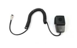
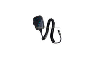
2. MICROPHONE
CONNECTION
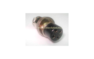
Insert the connector into the socket 4 pin team
respecting the guide notch. Then, thread
the clamp until it is firmly attached
TRANSMISSION
To transmit, hold the
PTT (located on the side of
micro) throughout the period
transmission. Correct, acting with the
MIC-GAIN for perfect
modulation. Respect, as far as possible, that the cord is
Extended.
3. CONTROL ON / OFF Volume (power and volume)
In the OFF position the transceiver is off. Turn this control to
the right to turn the unit. Continue turning slowly
clockwise to achieve the desired audio level. With the
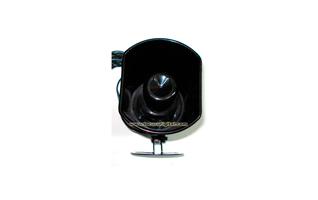
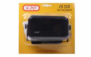
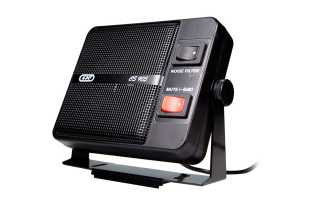
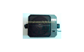
PA-CB switch in position PA, will handle the audio output level
by the external speaker (optional).
4. SQUELCH CONTROL (silencer)
For maximum receiver sensitivity, this control
adjusted exactly at the point where noise disappears
background.
5. RF-GAIN CONTROL (RF gain control)
Controls the sensitivity of the reception. To increase
sensitivity, turn right. The sensitivity decreases
turning it counterclockwise. The low sensitivity is useful when
signals on the channel are very strong.
6. MIC-GAIN CONTROL (microphone gain control)
TX mode, controls the amplification of the microphone. For
best results, use the original microphone and put it to Alan
optimal distance from your mouth (5-10 cm.) and the level of amplification
correct, asking his colleagues at what point
modulation is optimal.
7. SELECTOR ANL / OFF
ANL position activates an automatic noise limiter
caused by impulses (caused by motor car or other
sources)
ALAN BS 48 User's Manual 3
8. FIL-OUT SELECTOR
IDF position (beep) activates a tone control to get better
broadcast signals. OUT position (standing) the control is
disabled.
9. SWITCH CB / PA
In the CB position, the unit operates as a transceiver. You can use the
function PA (public address) only if its available
a speaker (optional) connected to the PA. In this case, the button
"Volume" controls the amplification.
3. INSTALLATION
The safety and ease are the primary considerations for
the mounting of any mobile equipment. All controls must
be easily accessible to the operator, without interfering in the correct
driving. Choose the perfect location in the vehicle
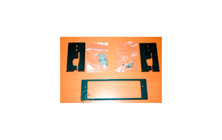
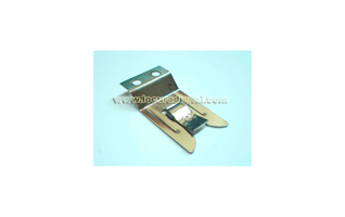
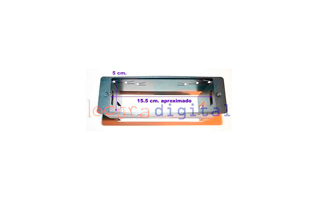
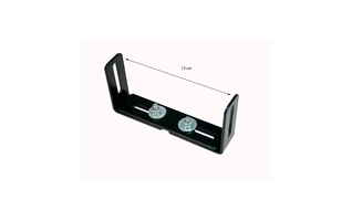
where to set the transceiver and use the supplied stand or, possibly, a
sliding support (optional). Put the screws. Support
attachment must be in contact with metal parts.
Note: we remind you that is absolutely forbidden to use microphones
handheld mobile communications (in vehicles). There are in
market "hands-free kits" that allow you to use the radio without the need
to remove his hands from the steering wheel, keeping the performance of equipment and
greatly increasing both their safety and that of other
drivers.
4. CONNECTION
Make sure the transceiver is off. In feeding
DC is very important to observe the polarity, even if
unit is protected against an accidental inversion:
Red = positive ( )
Black = negative (-)
The same colors are present in the battery and the box
Car fuse. Correctly connect the cable to the terminal
battery.
ALAN User Manual BS 48 4
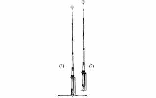
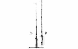
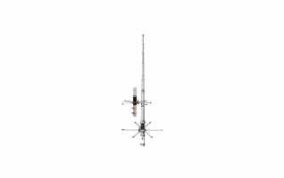
5. ANTENNA INSTALLATION
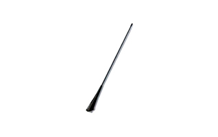
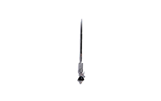
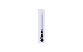
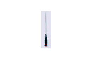
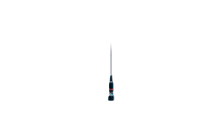
1. Install the antenna as high as possible. Follow the instructions given
the manufacturer.
2. Typically, the longer the antenna, enhanced performance
obtained.
3. If possible, mount the antenna on a large surface (roof) and
this center.
4. Keep the antenna cable shielded from noise sources such as
the ignition of the car, etc.
5. Make sure you have a solid grounding, metal
metal.
6. In the event that can not meet as described in the previous section,
we inform you that there are special antennas on the market not
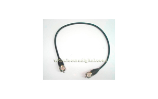
require a ground plane. Also on hand is a type of cable
antenna connection that simulates an artificial ground plane. In both
cases, installation can be achieved that performance
entirely satisfactory.
7. Avoid damaging the antenna cable during installation thereof.
Warning: To avoid causing serious damage to equipment, never operate
its radius without being connected to a suitable antenna.
We recommend periodic testing of the cable and the ROE
installation.
6. OPERATING TRANSCEIVER
1. Connect the microphone jack.
2. Make sure the antenna is connected to the computer.
3. Make sure the squelch control is turned fully
the left.
4. Turn the unit on and adjust the volume control.
5. Select the desired channel.
6. In the absence of signal, adjust the squelch (squelch) to eliminate
background noise.
7. To transmit, hold the PTT button and speak to about 10 cm.
the microphone and with a normal tone.
8. To receive, release the PTT.
